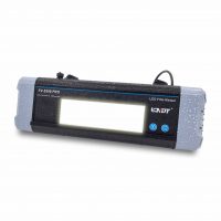
The JME portable X-Ray Betatron 7.5MeV is designed to produce high energy ionising radiation for industrial radiographic non-destructive testing. It can penetrate 30 centimeters of steel or 1 metre of concrete. Case study provided by JME Advanced Inspection Systems.
INITIAL CONCERN
The catalyst for this study was the concern that main structural I-beams at a Petrochemical facility could be suffering from degradation due to the fracturing of a fire-resistant concrete that was applied during installation. The initial goal is to locate possible damage caused by oxidation due to water ingress through the fractures that could affect the integrity of the structure as well as determine the extent of the damage revealed without the removal of the fire protectant.
COMMENTARY OF ANALYSIS

This paper will focus on the ability of high energy X-Ray photons to penetrate structural steel encased in fire proofing material. Based on the previous results, as demonstrated by the Iridium 192 image here and considering the energy levels associated, it is hypothesized that to penetrate a specimen consisting of a 12” I-beam with a web thickness of .750” and flange thickness of .500” encased in 14” x 16” fireproofing concrete, that energies of 2 MeV or greater will be necessary to reveal artificially induced degradation. These discontinuities consisted of 3 drilled holes .500” in diameter at 3 different depths 1/4t (.1875”), 1/2t (.375”), and 3/4t (.500”). These depths were chosen in an effort to simulate expected damage that could jeopardize the structural integrity of the beams at specific areas of concern.
PREVIOUS ATTEMPTS
When the concern was initially revealed, a concerted effort was made to radiograph the suspect area using digital radiography (DDA) and an Iridium 192 isotope and 400 KV X-Ray tube. While both Iridium and 400 KV were successful in producing an image, the image lacked definition and sensitivity to reveal the extent of the damage. It was noted the aggregate within the concrete drastically attenuated the photons of the radioisotope. After assessing the image, along with the procedure parameters, it was pondered that utilizing shorter wavelength photons, effectively reducing the amount of particulate interaction within the specimen, should provide the desired definition and sensitivity.
HYPOTHETICAL CONCEPT
During our attempt with Iridium 192 and 400 KV, it was discovered that the thickness and characteristics of the concrete drastically attenuated the photons in the bandwidth provided by the radioisotope and X-Ray tube, Iridium energies are composed of 10 distinct energies ranging from .21 to .61 MeV with the primary energy at .35 MeV, (there is some debate depending on the referenced material) and the spectrum upon energies found with the X-Ray tube at a maximum output of 400 KV. It is postulated that the longer wavelengths of these energies are being heavily absorbed within the cement, and significant buildup is causing excessive scatter to the image compromising sensitivity and definition. The basic principle here is to eliminate the excessive scatter by lessening the particulate interaction, electron/positron emission associated with the pair production principle and attempt to penetrate the specimen with photons in the 2 to 7.5 MeV range. Inherently, X-Rays produce an energy spectrum with the highest output at the maximum capacity of the accelerator. This spectrum, although consisting of all energies, possess bands of energies that have more intensity than other energies within the spectrum.
Taking notice of the primary bands of energies, it is realized that the primary bands decrease in wavelength as the energy is increased. The main spectrum, at any of the three energies listed, is not considered optimal. The primary bands are below or at pair production energy (1.02 MeV), which emit ionizing particles as well as photons that increase forward scatter, reducing definition and sensitivity. The options available to eliminate these unwanted energies are to; filter out the undesired energies, use the higher energy levels to increase the percentage of the desired energies to the digital detector array in the shortest time possible to reduce the forward scatter and eliminate particle interaction, or a combination of both. A series of tests were conducted using different combination of these options to determine which option provided the most optimal image quality. It should be considered that circular particle accelerators only function at a percentage of the tube potential when variable energy levels are selected. For example, when running a 7.5 MeV accelerator at 2.5 MeV the tube is only performing at 5% of the tube potential, when set to 5.0 MeV the tube is performing at 33%, and only 7.5 MeV is the output at 100% capacity. These tubes also pulse, so to gain maximum efficiency, synchronization of the detector and the tube would prove advantageous. For this exercise, the tube and the detector were not synchronized.
Fire proofing material: A fire retardant concrete could not be sourced; however, in an effort to conduct the testing, a cement/sand mixture with aggregate up to .5” was used. This particular mixture does not accurately represent the fire retardant used in the original specimen. As the retardant is known to be less dense than typical concrete and the aggregate is considerably smaller in size and less dense than the rock used, the mindset here, is that since concrete mixing is not an exact science and different materials may have been used for the creation of the concrete for different columns, if we are able to reveal the artificial damage within the blend that is more dense than the fire proofing sample provided, the probability of disclosing damage with less volume will be considerably higher; consequently increasing the sensitivity and definition.
INITIAL TESTING WITH HIGH ENERGY X-RAYS
SPECIMEN
I-Beam Dimensions:
Length: 12”
Width: 13”
Height: 12”
Web Thickness: .750”
Flange Thickness: .500”
Flaw Dimension 1/4t: Diameter .5” x Depth .1875”
Flaw Dimension 1/2t: Diameter .5” x Depth .375”
Flaw Dimension 3/4t: Diameter .5” x Depth .5625”
SIMULATED FIRE PROOFING MIXTURE
Length: 16”
Width: 14”
Height: 12”
TESTS
*Test #8 and #11 have been eliminated as there was no additional clarity or definition revealed in the image.
TEST 1
 Source to Object Distance: 36”
Source to Detector Distance: 53”
Object to Detector Distance: 17”
Focal Spot: .3mm x 3mm, .119”
Exposure in Seconds: 110
No. of Frames: 5
Megaelectron Volts (MeV): 2.5
Filters Applied: Edge DR 1
Comments: 2.5 MeV proved to penetrate the specimen at 110 seconds/frame. The 1/2t and 3/4t holes were visible; however, the excessive exposure time and inability to pull the 1/4t hole was unfavorable. It was decided to increase the exposure time to deliver more dose to the plate.
TEST 2
 Source to Object Distance: 36”
Source to Detector Distance: 53”
Object to Detector Distance: 17”
Focal Spot: .3mm x 3mm, .119” Diagonal
Exposure in Seconds: 200
No. of Frames: 5
Megaelectron Volts (MeV): 2.5
Filters Applied: Edge DR 1
Comments: 200 seconds proved to reveal all three holes, even at an excessive object to plate distance. This was tested, in the case, physical limitations did not allow the plate to be in intimate contact with the specimen. It was noticed during the site visit that there were a number of utility lines and the like supported by the beams that are intended to be evaluated during the investigation. Although positive results were realized, the exposure time was considered excessive, therefore the object to detector distance was lessened and source to object was increased.
TEST 3
 Source to Object Distance: 45”
Source to Detector Distance: 53”
Object to Detector Distance: 8”
Focal Spot: .3mm x 3mm, .119” .119” Diagonal
Exposure in Seconds: 115
No. of Frames: 5
Megaelectron Volts (MeV): 2.5
Filters Applied: Edge DR 1
Comments: Test 3 proved favorable with added definition and sharpness to the 1/4t hole; however, the exposure time was still not desired. It was decided to increase the MeV, decrease the source to object and decrease the time.
TEST 4
 Source to Object Distance: 30”
Source to Detector Distance: 38”
Object to Detector Distance: 9”
Focal Spot: .3mm x 3mm, .119”
Exposure in Seconds: 90
No. of Frames: 5
Megaelectron Volts (MeV): 5.0
Filters Applied: Edge DR 1
Commentary: Test 4 provided optimal definition and sensitivity, less mottling of the image was realized, which gave the precedence to increase the MeV to the maximum output of the tube and achieve 100% efficiency. It is deduced that the reduction in mottling is due to the decrease in wavelength as a result of the MeV increase.
TEST 5
 Source to Object Distance: 30”
Source to Detector Distance: 38”
Object to Detector Distance: 8”
Focal Spot: .3mm x 3mm, .119” Diagonal
Exposure in Seconds: 34
No. of Frames: 5
Megaelectron Volts (MeV): 7.5
Filters Applied: Edge DR 1
Comments: As one can see, the wavelength reduction decreased the forward buildup by decreasing the
probability of high energy photons interacting with the aggregate resulting in less mottling on the image. The main spectrum of energy (0 to 1.5 MeV) produced during a 7 MeV exposure is has very little effect when reducing the time of the exposure (imagine the decrease dose to the plate at 2.5 MeV for 115 seconds) however, the > 1.5 MeV photons produce enough interaction within the steel to lessen the concrete and aggregate effect to the image and consequently increase the steel’s effect on the image.
TEST 6
 Source to Object Distance: 30”
Source to Detector Distance: 38”
Object to Detector Distance: 8”
Focal Spot: .3mm x 3mm, .119” Diagonal
Exposure in Seconds: 25
No. of Frames: 5
Megaelectron Volts (MeV): 7.5
Filters Applied: Edge DR 1
Comments: Favorable effects when reducing the shot time and all other parameters are kept constant.
TEST 7
 Source to Object Distance: 45”
Source to Detector Distance: 53”
Object to Detector Distance: 8”
Focal Spot: .3mm x 3mm, .119” Diagonal
Exposure in Seconds: 40
No. of Frames: 5
Megaelectron Volts (MeV): 7.5
Filters Applied: Edge DR 1
Comments: Increased the source to object distance in an effort to increase the sensitivity, unfavorable results were witnessed. The longer the time the more scatter occurred which increased the mottling.
TEST 9
 Source to Object Distance: 45”
Source to Detector Distance: 53”
Object to Detector Distance: 8”
Focal Spot: .3mm x 3mm, .119” Diagonal
Notes: Rotated 90 degrees
Exposure in Seconds: 40
No. of Frames: 5
Megaelectron Volts (MeV): 7.5
Filters Applied: Edge DR 1
Comments: Although we do not intend to expose the specimen through the thicker cross section, it was decided to attempt one of these images. You will notice that on the bottom right-hand portion of the web of the I-beam there is a noticeable loss of material, this material loss is from a gouge (2.07 mm) ground into the web on the source side of the I-beam. This is a phenomenal revelation given that this discontinuity is being revealed through 13” of steel and is not noticeable through 13.250” of concrete and ¾” of steel. This is a real testament of the penetrating power of the accelerator and the scatter interruption when shooting through concrete.
TEST 10
 Source to Object Distance: 30”
Source to Detector Distance: 38”
Object to Detector Distance: 8”
Focal Spot: .3mm x 3mm, .119” Diagonal
Exposure in Seconds: 40
No. of Frames: 5
Megaelectron Volts (MeV): 7.5
Filters Applied: Edge DR 1
Comments: This exposure was taken to ascertain whether taking a radiograph through the long axis of the specimen would expose a 2 mm artificial discontinuity in the flange section of the I-beam. No discontinuity was revealed, this backs the theory that the scattering effects of the concrete are exponentially higher than any scatter that occurs within carbon steel. We can see a 2.07 mm indication through 13” of steel and approximately 2” of concrete but we cannot reveal a 2 mm discontinuity through 1” of steel and 15” of concrete.
TEST 12
 Source to Object Distance: 30”
Source to Detector Distance: 38”
Object to Detector Distance: 8”
Focal Spot: .3mm x 3mm, .119” Diagonal
Notes: ¼” Pb After holes drilled, one filled with water. 4 Leads placed on specimen side.
Exposure in Seconds: 90
No. of Frames: 5
Megaelectron Volts (MeV): 7.5
Filters Applied: Edge DR 1
Comments: In order to ascertain the sensitivity levels in the image and determine if the insulation was not in intimate contact with the part, which could consequently allow and retain water ingress, an 8mm hole was drilled into the part to simulate this scenario. To eliminate any excess scatter approximately 1/4” of Pb was first placed on the source side of the part for the examination. The drilled hole was visible; however, it was believed that placing the filter at the detector side of the plate would prove favorable.
TEST 13
 Source to Object Distance: 30”
Source to Detector Distance: 38”
Object to Detector Distance: 8”
Focal Spot: .3mm x 3mm, .119” Diagonal
Notes: ¼” Pb Leads on detector side after holes drilled.
Exposure in Seconds: 90
No. of Frames: 5
Megaelectron Volts (MeV): 7.5
Filters Applied: Edge DR 1
Comments: As hypothesized, placing the filter on the detector side of the plate proved to reveal favorable results. The drilled 8mm hole is clearly seen the image.
SUMMARY
As postulated, using a high energy particle accelerator was indeed successful in revealing the ¼ t, ½ t, and ¾ t holes in the specimen. Improved definition and sensitivity were witnessed at the higher energy levels as the higher energies allowed for less exposure time which decreased the forward build-up typically associated with longer exposure times and lower energies. Pb filters of ¼” at the detector proved to be an appropriate filter to increase sensitivity levels which enabled the detection of not only ¼ t x ½” diameter hole, but also revealed an 8mm hole within the concrete itself. It is believed that the sensitivity achieved is more than adequate to assess the integrity of the structural I-beam; however, after obtaining the data, it is recommended that engineering calculate the criticality of the degradation.
Contact us for more information on the JME PXB:7.5 Betatron.