Description
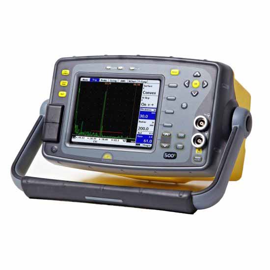
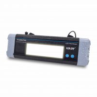
Sitescan 500S Flaw Detector
- Customisable & Inituitive Menus
- Split DAC/AVG/DGS
- Angle Measurement Mode.
- Configurable on-board software.
- Field Upgradeable.
- Encoded B-Scan
- A-Scan Fade.
- 4GByte on-board memory.
- USB Interface for PC import/export.
- Video Output for training.
Sizing Techniques & Software Options include:
DAC (Standard)
Defined by up to 20 reference points or converted from TCG curve and digitally drawn on the screen. DAC curves meet the requirements of EN1714, ASME, JIS and many other standards. Custom DAC curves can be selected. DAC dynamic range can be extended by automatically adjusting the reference curve to match the reference gain. Scanning Gain and T-Loss available as separate controls. Amplitude readout is selectable between %FSH, % DAC or relative dB.
Split DAC & DGS/AVG (Option)
Adds up to 3 zones of added gain (+12db, +24dB) to the DAC or DGS/AVG curve to enable single-pass scanning of large sections and attenuative materials. Conforms to EN583-2:2001.
TCG (Option)
Time corrected or “Swept” gain, defined by up to 10 reference points or converted from a DAC curve. All points converted to 80% screen height.
Backwall Echo Attenuation (BEA) Option (requires TCG)
0-40dB attenuation applied to the latter part of the time base, to improve the detectability of defects near the back wall and the loss of BWE due to porosity.
AWS (Option)
Built-in calculation and display of factors and parameters required by AWS D1.1
AVG/DGS (Option)
Enables the calculation of pseudo “DAC” curve and equivalent reflector size of UT indications, based on user input of transducer parameters.
API (Option)
On-board flaw sizing method in accordance with API 5UE.
Interface Trigger (Option)
Unlocks the interface trigger gate controls, which hold off the A-Scan acquisition and display until an interface echo is detected within a specific range and amplitude. Used for the elimination of water-path.
Corrosion Software (Option)
Enables complex inspection plans to be uploaded from a PC using the on board UTility software. Features include 2 dimensional thickness logging, storing A-Logs and B-Logs with thickness values, taking multiple readings per location and note creation for each grid location. A B-Scan option available to display bar-graph views of thickness readings taken by Gate 1 against distance or time.
Test Range 0-5mm(0.25in)up to 0-10,000mm (400 in.) in steel at 5930m/s (19455f/s)
Velocity 1000 – 10,000 m/s continuously variable.
Probe Zero 0 to 999.999 µs.
Delay 0-10,000m (400in) in steel at 5930m/s (19455f/s)
Gain 0 to 110dB adjustable in 0.5, 1, 2, 6,10, 14 and 20dB steps.
Test Modes Pulse echo and transmit/receive.
Pulser 200V fixed. 50nS square wave. Rise/Fall times <5nS into 50R load.
Damping 50 and 400 Ohm damping selectable.
Active EdgeTM Unique Active Edge Mode for improved near-surface resolution.
P.R.F Adjustable 5Hz to 1kHz. External sync also available.
Rectification RF, Full wave, +ve half-wave and -ve half-wave.
Frequency Range 1.0MHz to 14MHz
System Linearity Vertical = 0.5% Full Screen Height (FSH). Horizontal +-0.2% Trace Full Screen Width (FSW).
Display Colour Transflective VGA (640 x 480) TFT. Display area: 116.16 x 87.2 mm (4.57 x 3.43 in).
A-Scan Area: 400 x 510 pixels (normal), 460 x 620 (FS).
Gate Monitor Two independant gates for measurement and monitoring. Start and width fully adjustable over the entire range of the instrument. Levels adjustable from 0% to 100%, positive ornegative triggering on each gate with audible & visual alarms. Gate resolution is 5nS.
Zoom Expands range and delay to cover the area set by Gate 1 start & width controls.
AGC Automatic Gain Control automatically sets the signal in Gate 1 to a level between 10% and 90% FSH, tolerance between 5% and 20%.
Measurement Modes
Mode 1 Signal monitor, Gate alarms can be active but no measurements are displayed.
Mode 2 Depth and amplitude of first signal in gate.
Mode 3 Echo-Echo distance measurements.
Mode 4 Trigonometric display of beam-path, surface distance (including X-offset) and depth of indication from the inspection surface together with echo amplitude. Curved surface correction can be applied for convex and concave surfaces. Half-skip can be indicated on screen.
Mode 5 Gate to Gate distance measurement
Mode 6 Flank to Flank
Mode 7 Beam Angle, calculated from beampath, hole radius and hole centre depth.
Sitescan 500S Accessories
Sitescan Standard Kit
Sitescan 500S Digital Flaw Detector
Battery, Charger, charger mains cable.
User Guide & Calibration Certificate.
Certificate of Conformance
Carry Bag.
UT-lity & USB cable.
Display Window Cover.
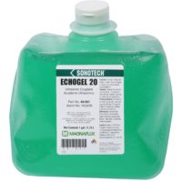
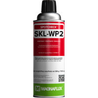
Ultrasonic Couplant.
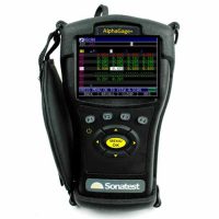
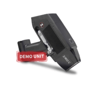
B-Scan Encoder Option
The Sonatest series of flaw detectors are suitable for Corrosion Mapping using linear encoded scanners like the EZ-scan 4 (as seen on the right).
Ideal applications include Storage Tank bottom and side walls, flat plates and pipes with a 10cm (4”) or greater outside diameter.
Rubber Boot Accessory
Customised Rubber “shell” that fits around the instrument for extra protection and insulation. (D-50 only)
UT-lity Pro (Advanced User Software)
UT-lity Pro is the “professional” version and works in conjunction with the Corrosion Software option, providing the end user with the ability to create and manage inspection plans, location notes, historical thickness readings and other asset management information as required.
• Set up Inspection plan (grid) templates, notes and labels.
• Import previous readings into an inspection plan
• Export Inspection plan data to spreadsheets and plant maintenance databases.
Click Here for more information


Reviews
There are no reviews yet.